
Open frames
Continuous mounting edges connect covers or adjacent equipment; thin spans may require support during machining.
Explore open frames and deep structural housings through their actual geometry, mounting interfaces and drawing requirements.
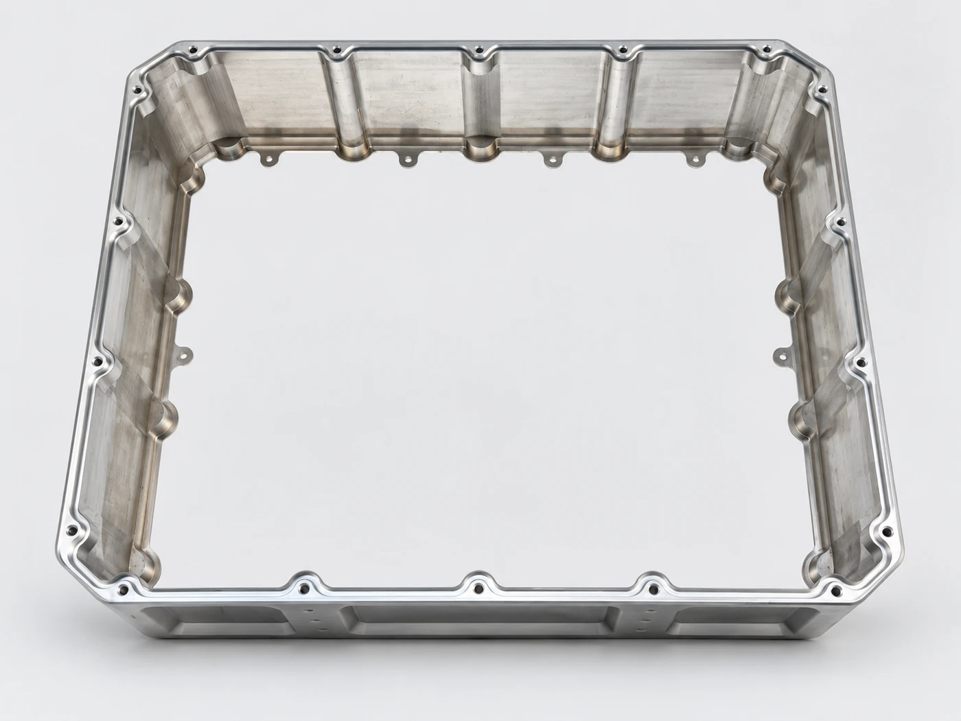
Product selection starts with the mounting geometry. Machining capacity and transport planning remain on the dedicated large-part service page.
Continuous mounting edges connect covers or adjacent equipment; thin spans may require support during machining.
Internal ribs connect the perimeter to mounting locations while preserving clearance for components.
An end flange and side openings bring several interfaces into one body. Their datum relationship needs to be explicit.
| Recommended quotation detail | Overall dimensions, material condition, key interfaces, finish and quantity. |
|---|---|
| Product photo use | Photos illustrate geometry; material grade and performance are defined by the project drawing. |
The photograph shows the actual open structure. Use the drawing to define the mating and locating requirements.
Review the mating surface, hole locations and any cover or adjoining component together.
Identify the remaining section and clearance needed around ribs and corners.
Define the relationship between side interfaces and the main mounting reference.
A different structural family, reviewed against its own assembly requirement.
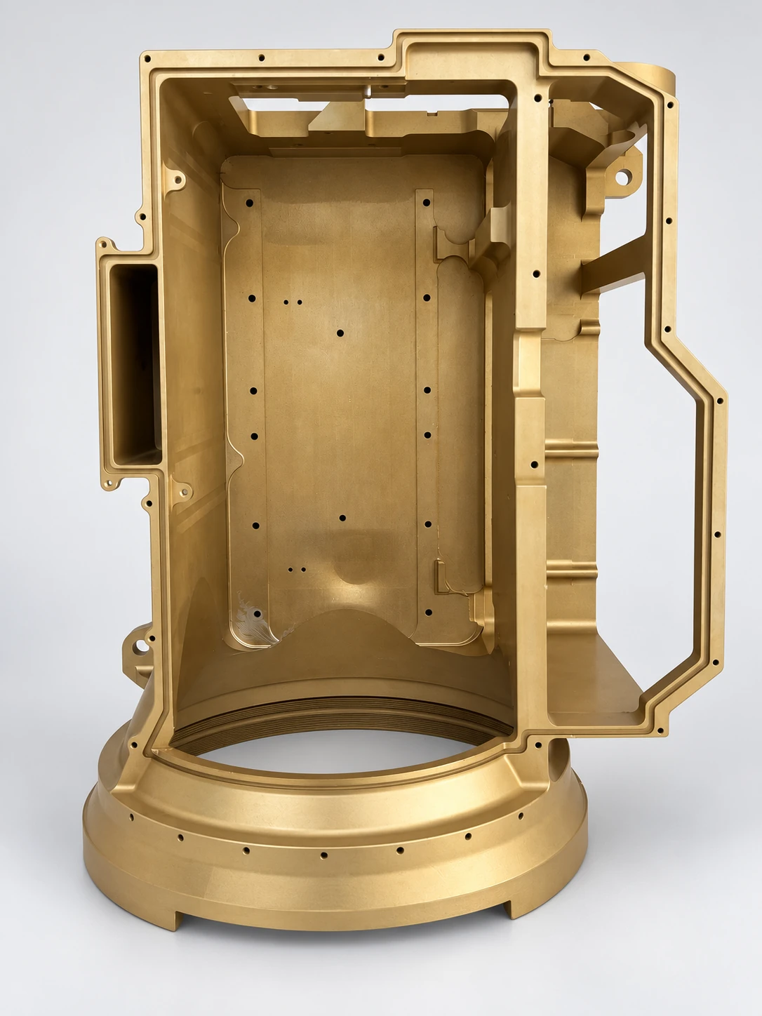
The supplied part combines a deep cavity, local pockets, side openings and a circular end interface. Review internal access and the relative position of the mounting features.
The photographs identify structures; they do not establish measured dimensions or a universal tolerance.
Begin with the structure and its installation function.
No. A frame describes the geometry; overall size and setup space determine whether large-part manufacturing review is needed.
Use an approved drawing or model. Photographs support discussion of structure, not dimensional acceptance.
The separate large-part service page explains the review envelope, workholding, datum transfer and transport considerations.
Review the machining envelope, support, setup transfers and protective delivery on the dedicated service page.
Explore large-part machiningPart number and revision → feature and datum → sample and batch → instrument and measured result. Agree the required records with the order.
Review inspection records