
Ribs & thin sections
Balance tool access and rigidity. Plan support and cutting sequence around wall distribution and the released condition.
Complex geometries, thin walls and multi-face interfaces. Custom structural parts that locate, connect and support an assembly.
Get a quote for your drawing ↗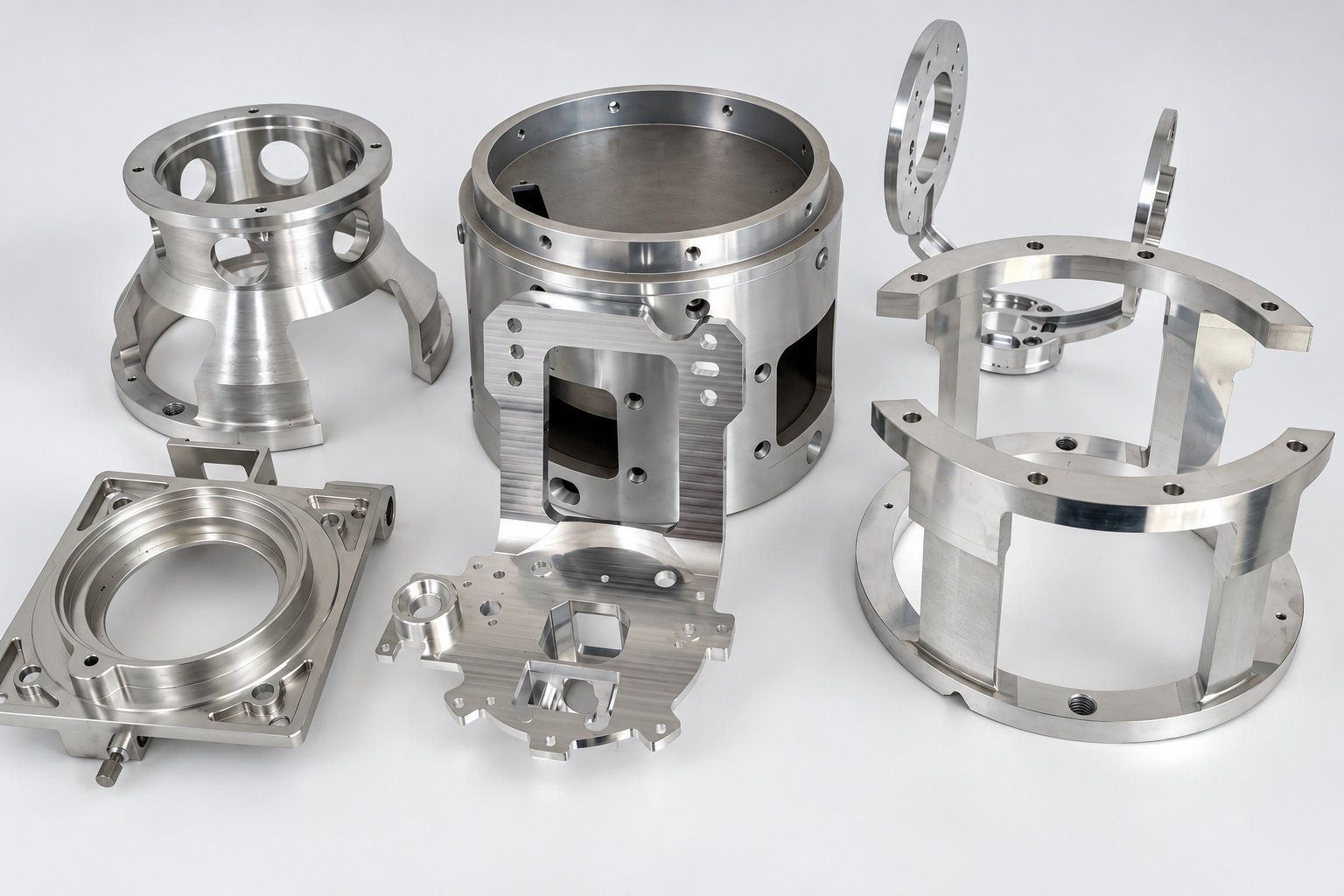
Real samples show ribs, openings, curved surfaces and mounting interfaces. Each geometry needs its own setup and feature checks.
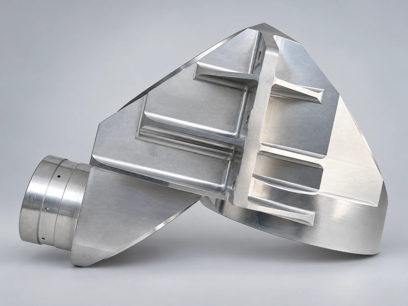
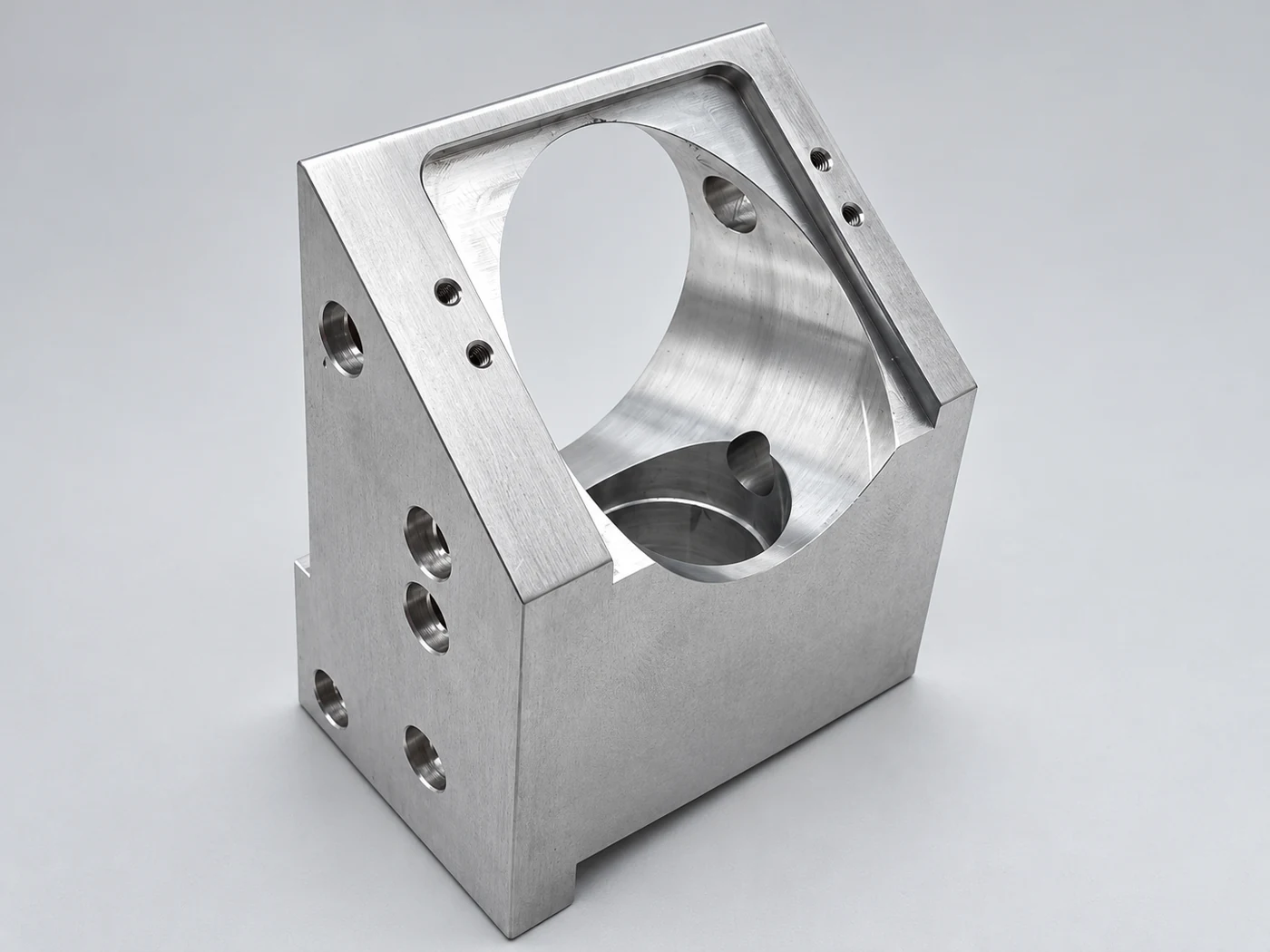
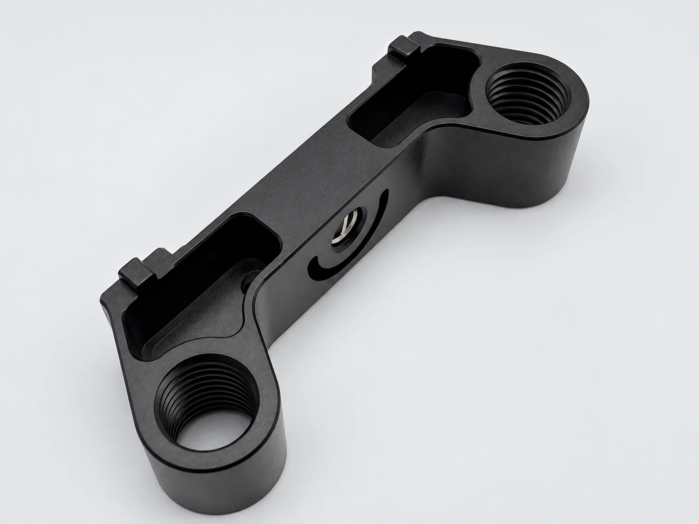
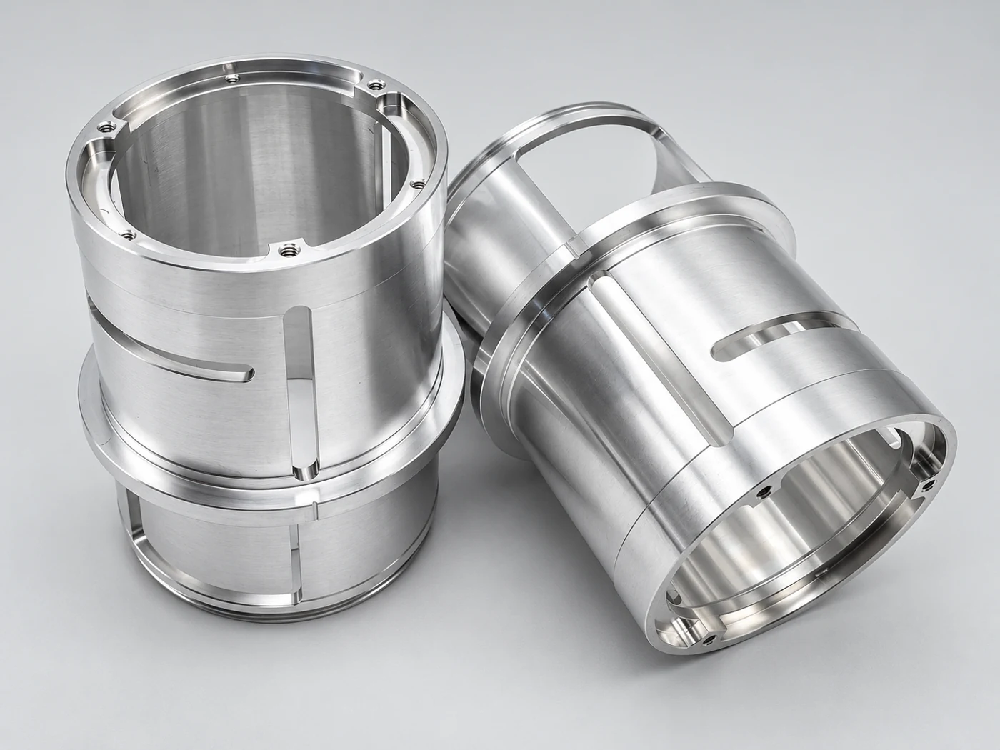
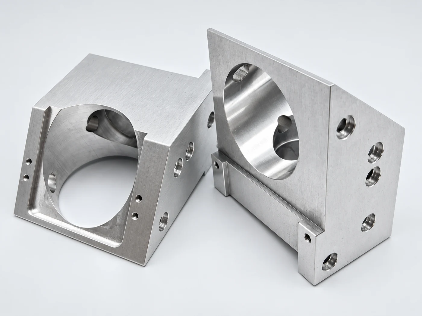
Critical features guide the process and inspection plan.
Balance tool access and rigidity. Plan support and cutting sequence around wall distribution and the released condition.
Keep locating features consistent across setups so the mating faces and holes remain related.
Review cutter reach, corner radius, chip evacuation and access for deburring.
Identify which features carry loads, locate other parts or provide clearance. Apply tolerances by function.
Dimensions and tolerances belong to the specific component. The photographs do not imply unverified material grades or measured results.
| Material options | Aluminum alloys, stainless steel and steel; specify grade and condition on the drawing. |
|---|---|
| Size and geometry | Provide overall dimensions and a 3D model; access and workholding are reviewed with the geometry. |
| Critical tolerances | Mark datum relationships, fits and positional or geometric requirements on the 2D drawing. |
| Surface finish | As-machined, bead blasting, anodizing or other specified treatments, with masking where needed. |
| Quantity and delivery | Prototype, small-batch or repeat orders; quote against the released drawing and quantity. |
Describe the mating component and the function of each interface.
Connect locating faces, sensor or actuator mounts and adjoining modules.
Review mounting access, replacement space and alignment between components.
Prioritize the interfaces that determine installation and performance.
Use feature numbers and a defined datum system to connect machining and inspection.
Agree whether critical checks apply before or after finishing and assembly.
The route follows the geometry, quantity and agreed acceptance requirements.
Confirm material, datums, fits, finish and quantity.
Plan stock, supports, setups and critical finishing operations.
Machine the geometry and clean edges without changing functional features.
Check specified features and protect contact surfaces for shipment.
Use the quotation discussion to distinguish essential requirements from avoidable complexity.
Deep narrow features, thin walls and multiple setups add machining and inspection work.
Localized critical tolerances and clear masking notes help focus work where it matters.
A 3D model and dimensioned PDF provide a useful starting point.
Yes, define the sample approval features and keep the released revision consistent for subsequent production.
STEP or IGES for geometry, plus a PDF drawing for tolerances, material, finish and revision.
Send your drawing, material, quantity and required delivery date.