
Internal corners
A rotating cutter leaves an internal radius. Where assembly permits, a larger radius improves tool access; sharp internal corners may need another process.
Explain the functional geometry, datums, material and acceptance conditions alongside your 3D model.
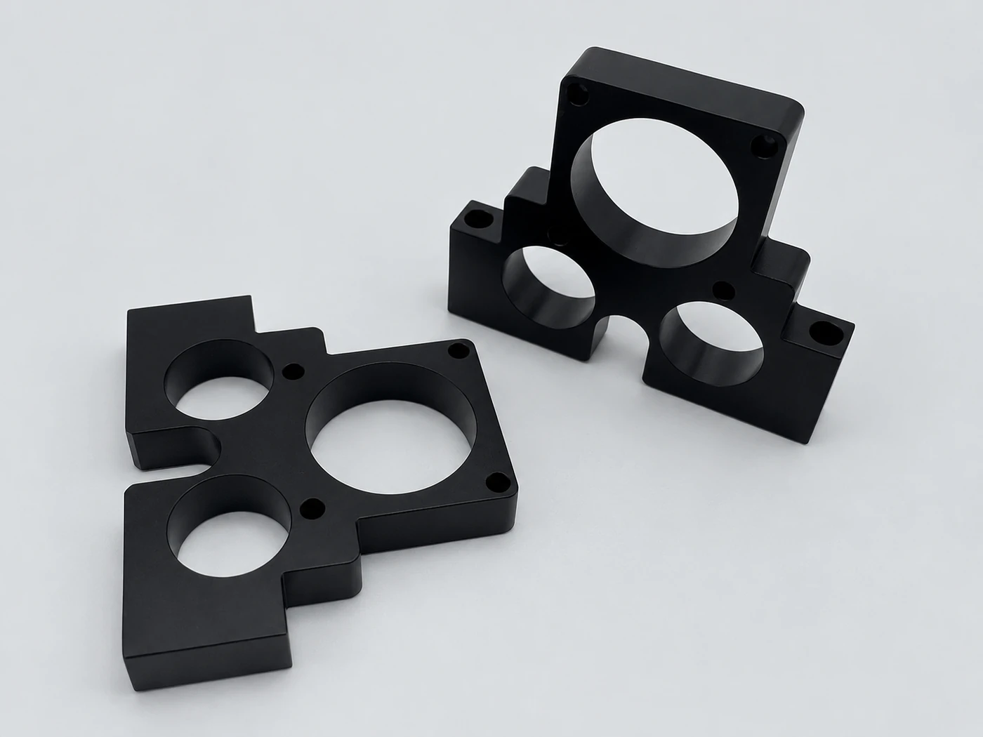
Use the drawing to connect datums, hole patterns and the mating condition.
Use these geometric checks before requesting a quote. They are design discussion points, not universal manufacturing limits.
A rotating cutter leaves an internal radius. Where assembly permits, a larger radius improves tool access; sharp internal corners may need another process.
Deep narrow features restrict tool reach. Thin sections may move during cutting or after release, so identify the functional requirement.
Specify thread standard, effective depth and whether the hole is blind. Avoid requiring unnecessary tolerance on clearance features.
| Illustrative revision | Where the assembly permits, changing an internal corner from R0.5 to R3 can allow a larger cutter; review the full geometry. |
|---|---|
| File package | STEP/IGES geometry + dimensioned PDF + material, finish, quantity and revision. |
Geometry, written requirements and revision identity need to describe the same part.
Review prompts, not universal minimum dimensions or a fixed SANHE tolerance table.
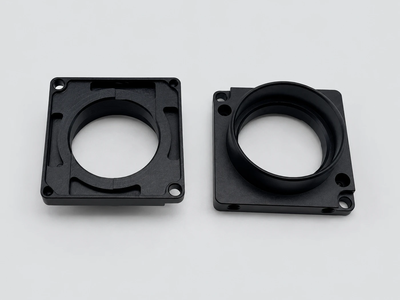
The supplied locating plates show openings, steps and corner features. Connect them to datums and the intended mating relationship on the drawing.
| Feature | Why review it | What the drawing should show |
|---|---|---|
| Internal corners | A rotating cutter leaves a radius; deep pockets also constrain cutter reach. | Permitted internal radius, mating clearance and relief options. |
| Thin walls and ribs | Low stiffness and material removal can affect machining and measurement. | Remaining thickness, sensitive features and free/supported acceptance state. |
| Deep holes and threads | Tool access, effective engagement and blind-hole clearance need separate review. | Hole depth, effective thread depth and thread specification. |
| Multi-face locations | Re-clamping transfers the locating reference between operations. | Datum hierarchy and the functional relationship between faces. |
State the function of the critical feature instead of applying the tightest limit everywhere.
| Requirement type | Useful definition | Related review |
|---|---|---|
| Size tolerance | Mark the functional size and the required limits or fit designation. | Material, machining route and final treatment condition. |
| Geometric relationship | Define the controlled feature, reference datums and applicable geometric requirement. | Locating, setup transfer and measurement references. |
| Surface texture | Identify functional areas needing a stated roughness or texture requirement. | Cutting approach, finishing and inspection method. |
| Final-condition acceptance | State any masking and whether dimensions apply after finishing or assembly. | Finish allowance, support and acceptance sequence. |
The supplier should not have to infer which file is approved.
Use the same part number and revision for model, drawing and written requirements. Clearly identify draft material.
List conflicting dimensions, unclear notes or model/drawing differences and confirm the governing requirement.
Identify what changed and which quantity or batch the change affects before revised work enters production.
A brief clarification before cutting can prevent a wrong interpretation.
Yes, for an initial discussion. Critical fits, datums, threads, material and finish requirements still need written confirmation before production.
Any proposed design change must be agreed before manufacturing. Identify features that cannot be changed for assembly or function.
PDF, STEP/STP, IGS/IGES, ZIP, JPG and PNG. The enquiry form shows the per-file and total-size limits before submission.
Include quantity and delivery needs; use the NDA route first when confidentiality needs agreement.
3D model + 2D drawing + part/revision + alloy/condition + quantity + finish/masking + critical features + delivery/records.