
Machined structure
Define the load-bearing or locating parts: base plates, housings, frames and mounting brackets.
CNC components remain the primary focus. Review related sheet metal, tooling and finishing needs within the actual manufacturing scope.
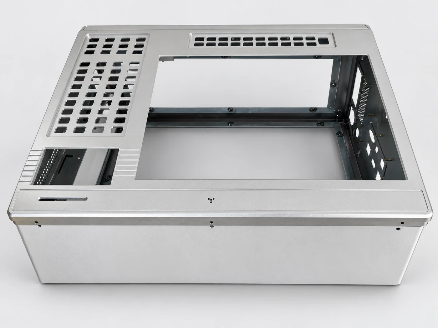
Review formed features, mounting interfaces and the agreed supply scope together.
A project may combine machined interfaces, formed covers and selected surface treatments. Organize the enquiry by final assembly rather than by isolated parts.
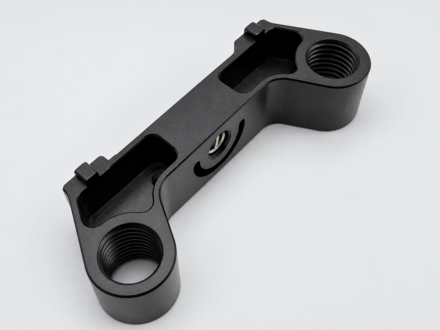
Define the load-bearing or locating parts: base plates, housings, frames and mounting brackets.
Review sheet-metal covers against openings, fastener access and the final assembly space.
Use an assembly drawing and bill of materials to connect quantities, finishes and supplied components.
| Assembly pack | Assembly view + numbered part list + individual drawings. |
|---|---|
| Interface check | Mating faces, hole patterns, assembly order and finish allowances. |
Review material, thickness, bends, welding, inserts, finishing and assembly interfaces.
Confirm flat patterns, forming details and critical interfaces.
Confirm in-house and coordinated processes for each project.
Mould categories, manufacturing scope and trial facilities must be confirmed before a tooling commitment.
Part drawings, material, volume, equipment and delivery scope.
Engineering review, design approval, samples and agreed delivery documentation.
Confirm actual processes, masking, cosmetic requirements and post-finish inspection responsibilities.
Identify cosmetic and mating areas in the drawing.
Some finishing is coordinated with external suppliers; the final scope must be stated accurately.
Related processes are reviewed per project, including the split between in-house and coordinated work.
| Supporting requirement | Review inputs | Acceptance interface |
|---|---|---|
| Sheet metal with machined parts | Thickness, bend direction, insert locations and mating models. | Assembly clearance, hole alignment and finished surface condition. |
| Fixtures and tooling | Intended use, part drawings, quantity and equipment interfaces. | Design approval, trial/sample requirements and agreed delivery contents. |
| Coordinated finishing | Finish specification, cosmetic sample, masking and material condition. | Colour/texture references, final fits and inspection responsibility. |
A matching set needs more than separately accepted parts.
Provide the assembly model, part numbers and the interfaces that need to fit together.
Confirm which processes, supplied items and checks are included, including any external coordination.
State whether parts are delivered separately or as an agreed assembly, with required identification and protection.
Describe the actual project before selecting a process.
No. Some processes, including finishing, are coordinated externally. The specific manufacturing split is confirmed with the project scope.
A photo can start a discussion. Drawings, material, quantity, mould type and trial conditions are needed before making a tooling commitment.
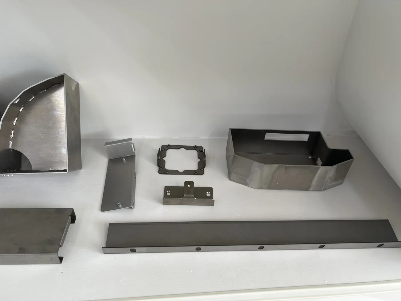
Photographs show supplied physical samples. Specific dimensions, material grades and results are agreed per project.
Send your drawing, material, quantity and required delivery date.