
Deep-pocket housings
Review cavity access, inner corners and remaining wall sections before selecting the machining route.
Complex pockets, thin walls and multi-face interfaces for precision equipment.
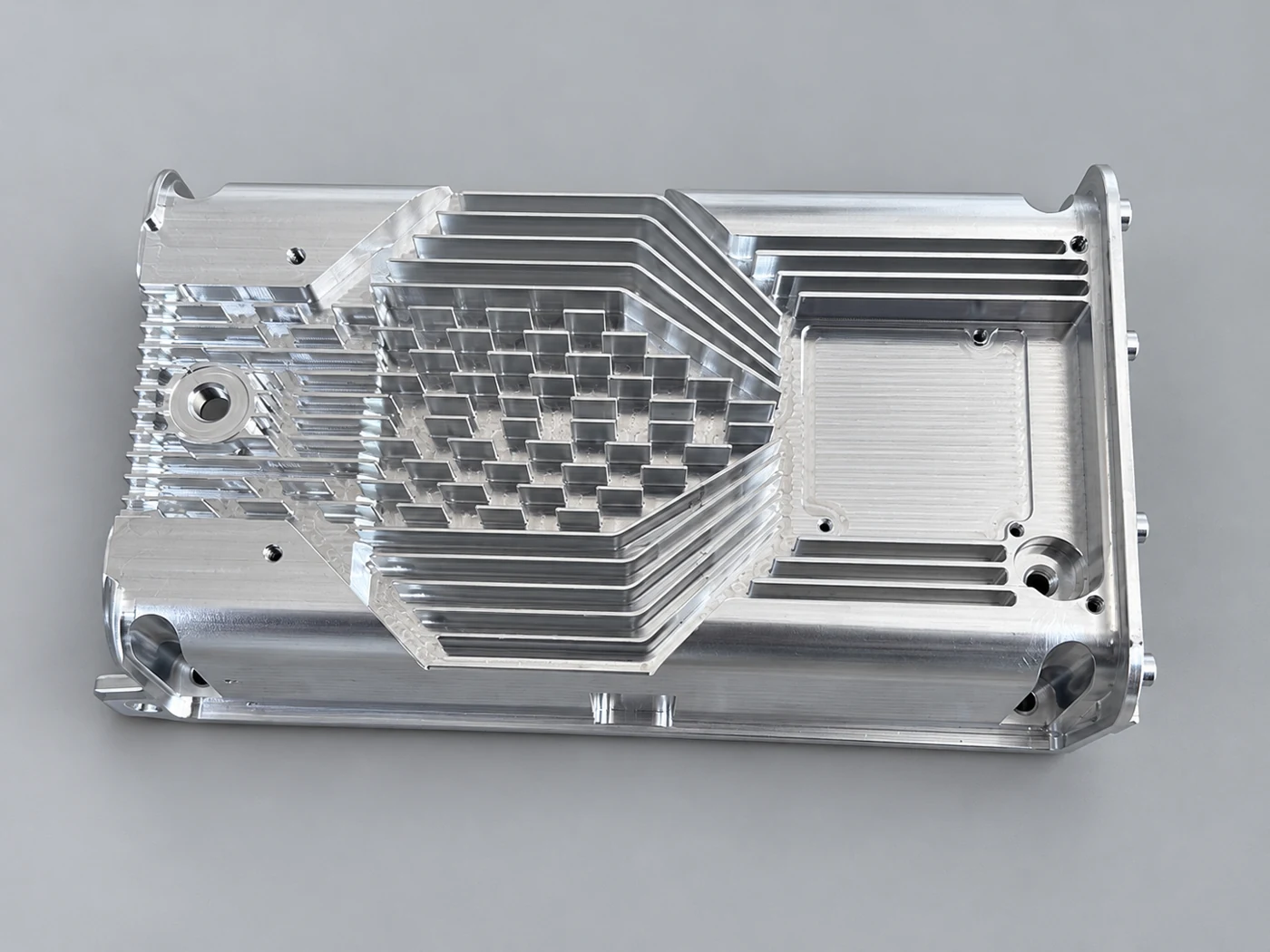
A housing can protect components, locate internal assemblies and connect multiple interfaces. These sample structures illustrate different design priorities.
Review cavity access, inner corners and remaining wall sections before selecting the machining route.
Closely spaced ribs and grooves need tool clearance and planned deburring access.
Identify mounting faces, cover holes and any specified sealing groove independently from cosmetic surfaces.
| Recommended quotation detail | Overall dimensions, material condition, key interfaces, finish and quantity. |
|---|---|
| Product photo use | Photos illustrate geometry; material grade and performance are defined by the project drawing. |
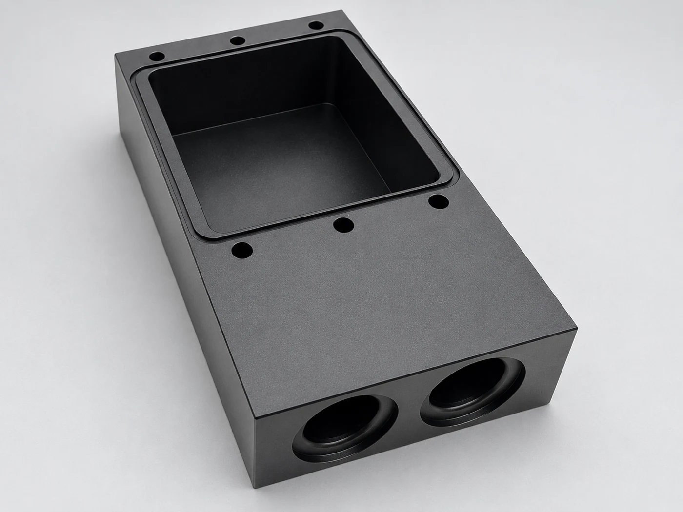
| Part types | Equipment housings, cavities and covers |
|---|---|
| Material | Aluminum alloys; grade and condition per drawing |
| Dimensions & tolerances | Cover fit, mounting features and post-finish dimensions. |
| Surface finish | As-machined or specified finish; colour and masking per project |
| Order type | Prototype, small batch and repeat orders |
Machine deep pockets, ribs, steps and internal mounting features.
Plan support and cutting sequence around thin walls and material removal.
Check cover fits, hole locations, threads and finished mating surfaces.
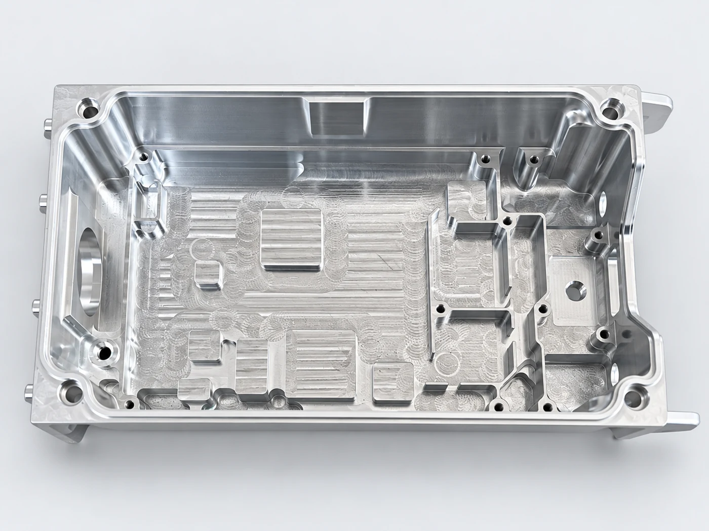
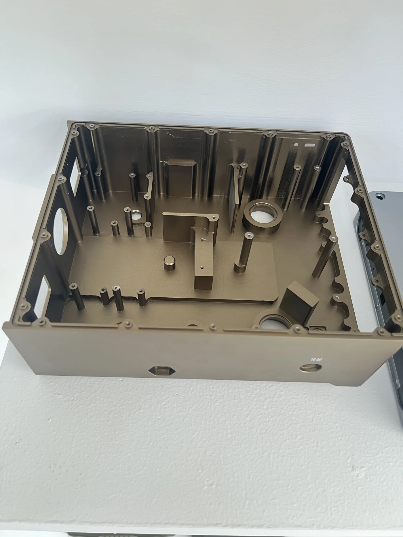
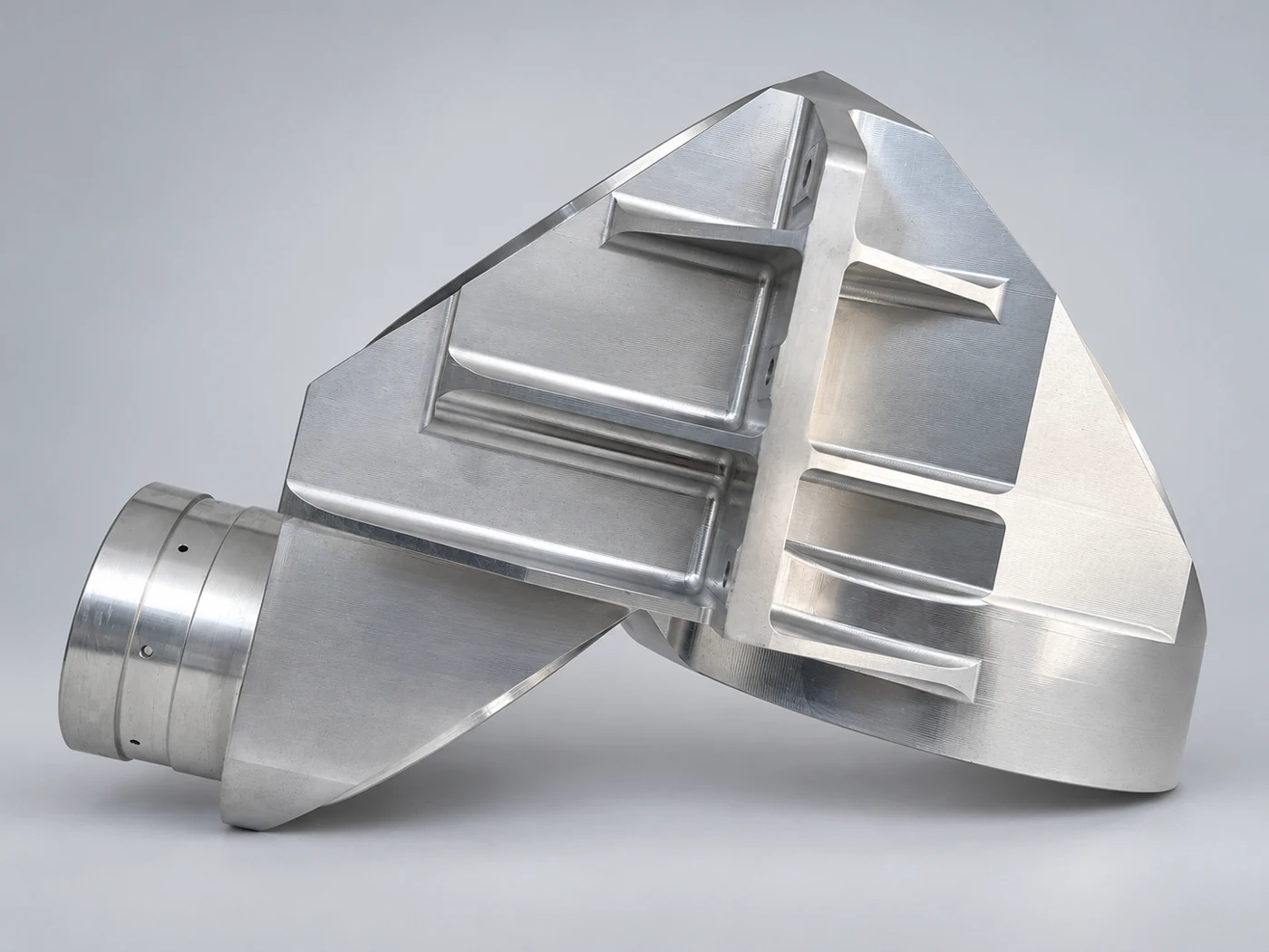
Housings and covers around internal components, cable interfaces and mounting points.
Include with your drawing: Internal layout, interface locations and designated cosmetic faces.
A photographed component illustrates the review priorities for similar geometries. The process below describes engineering considerations, not a historical production report.
Closely spaced ribs and grooves, pocket transitions and holes are visible in the supplied photograph. The drawing defines their dimensions and function.
Review groove clearance, internal radii and tool reach together. Assess support locations and the machining sequence around slender sections before selecting the process route.
Use the mating requirements to establish drawing datums. Agree checks for hole relationships, groove geometry and edge condition, including access for measurement and the final finishing condition.
Send the current 3D model and 2D drawing, material and finish, quantity and requested date. Mark critical features and required records so the review can identify open questions and quotation scope.
Plan the route around the functional requirements of this part family.
Identify the cover, mating components and surfaces that locate the housing. Confirm where a 2D drawing governs the 3D model.
Review remaining wall sections, pocket access and datum transfers before choosing the operation order.
Check the agreed dimensions and threads; where finishing changes a fit, specify the final-condition check.
Confirm the included operations, acceptance and supply stage so the quotation describes the part you actually need.
Clarify the requirements that are easily missed in a model alone.
A rotating cutter leaves an internal radius. Show the required radius or mating clearance so tool access and any relief can be reviewed.
State whether acceptance is in a free, supported or assembled condition. Clamping can change the apparent shape of a thin section.
No. Specify the alloy, sealing design and any required test independently. A housing photograph does not establish an IP rating.
Part number and revision → feature and datum → sample and batch → instrument and measured result. Agree the required records with the order.
Review inspection recordsSend your drawing, material, quantity and required delivery date.