
01
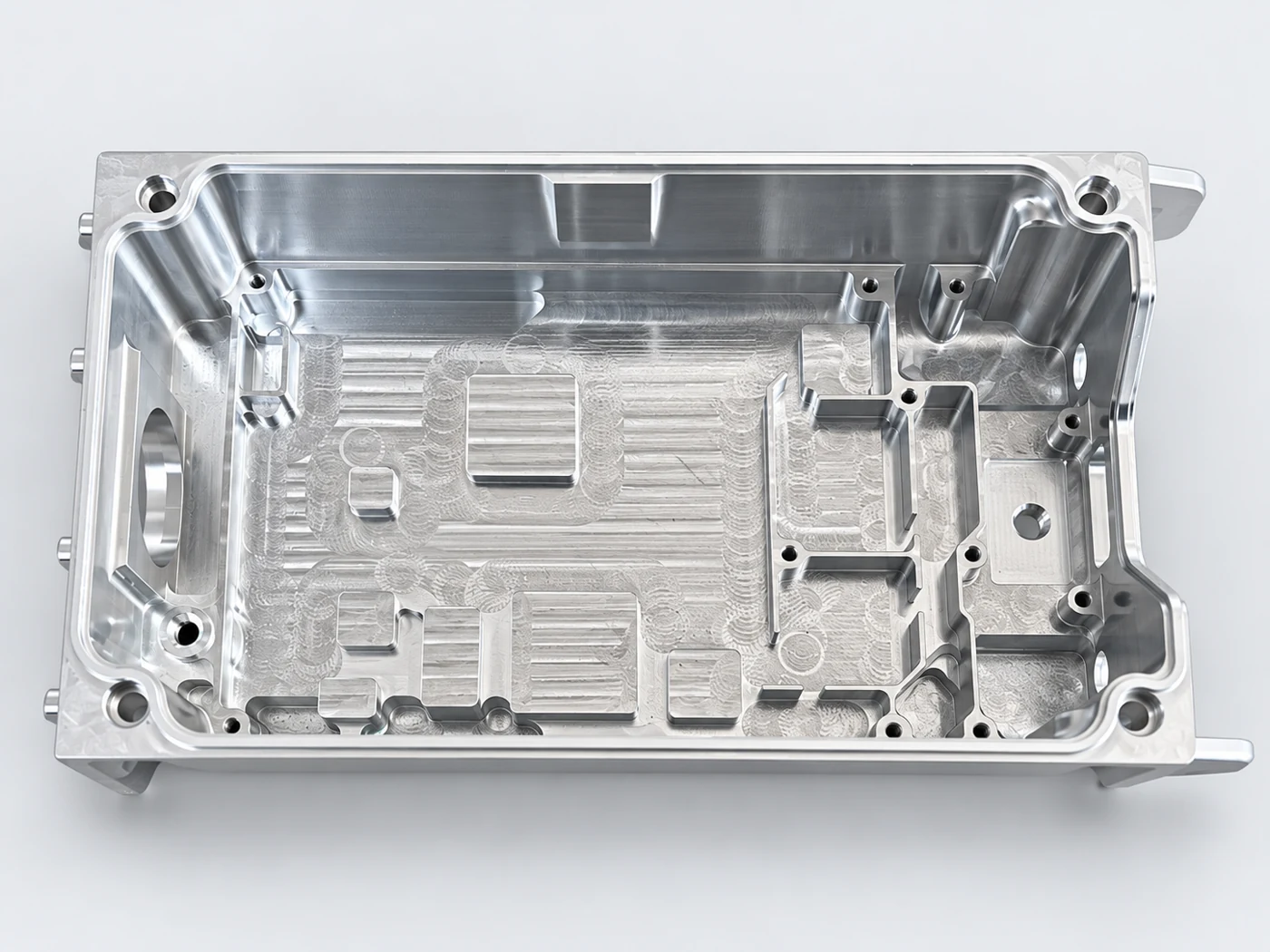
Housings & cavities
Pockets, ribs and cover interfaces. Plan tool access, wall support and datum transfer together.
Explore this capabilityCNC machining for complex ribbed components, long cavities, housings and mounting parts. Review tool access, support and multi-face datums together, then coordinate finishing and inspection.
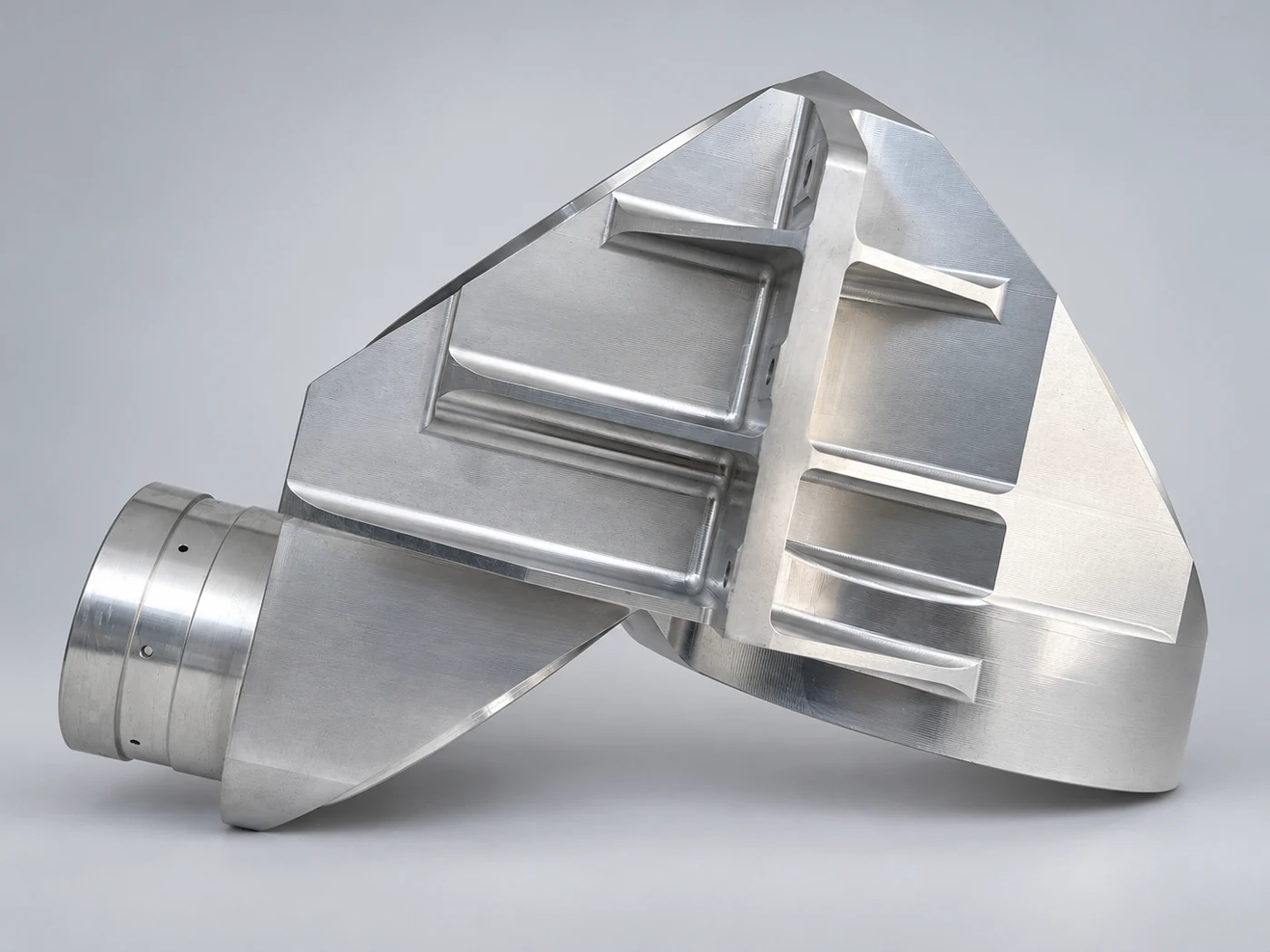
Milling, drilling, threading and multi-face machining are planned around the features that matter to the finished assembly.
Pockets, ribs and cover interfaces. Plan tool access, wall support and datum transfer together.
Explore this capability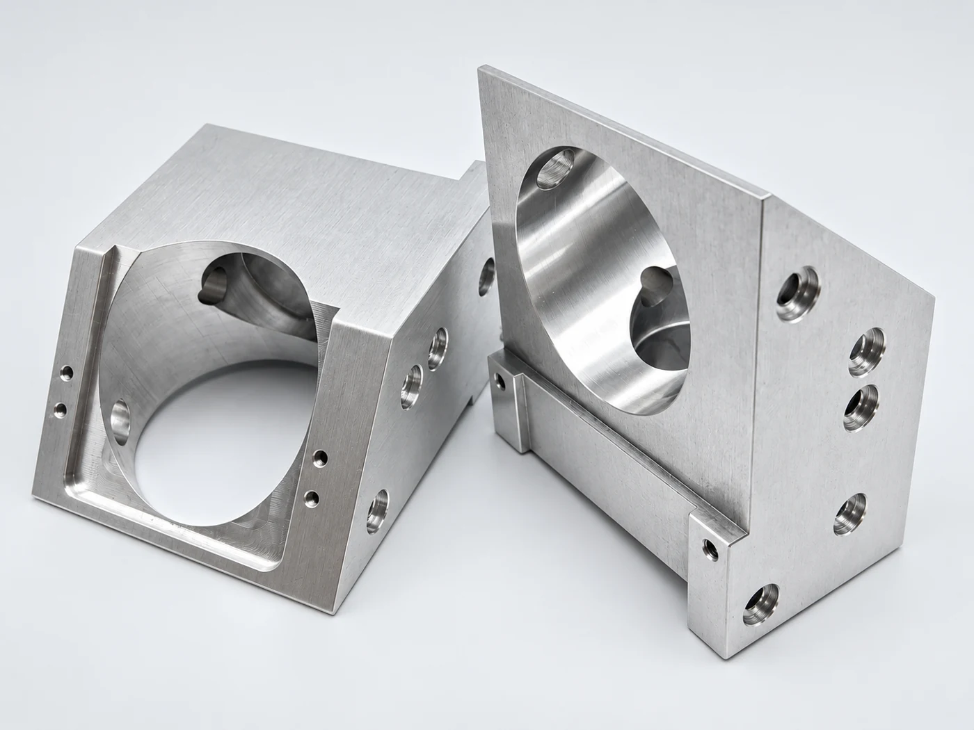
Steps, locating holes and threads. Keep critical mounting features aligned across machined faces.
Explore this capability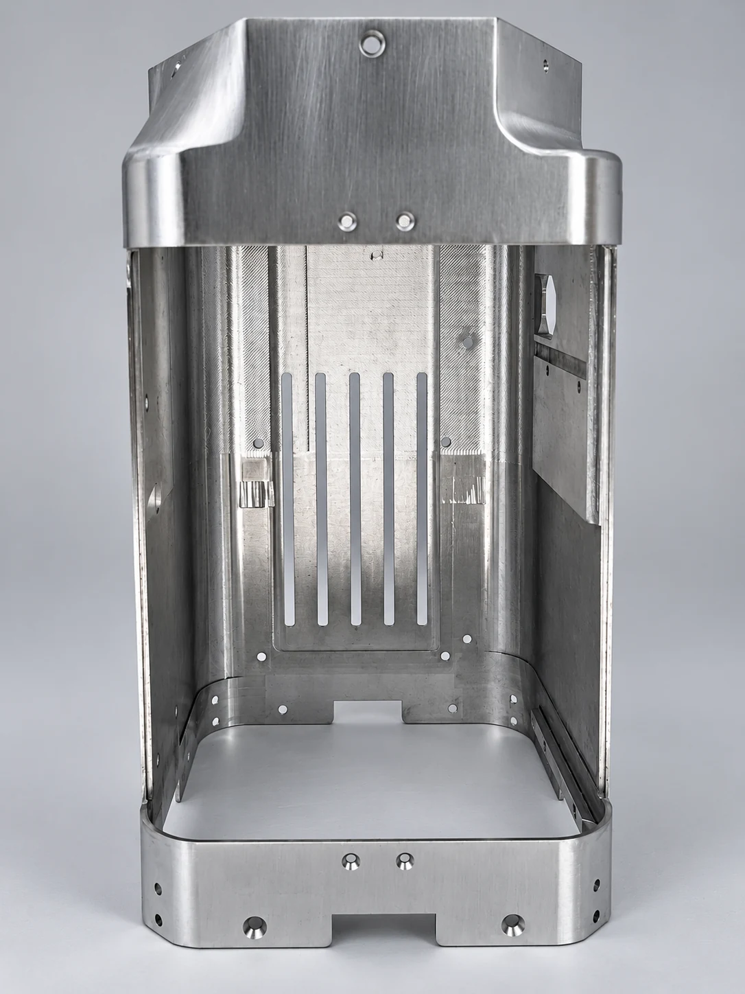
Contoured ribs, long cavities and side interfaces call for coordinated access, support and datum planning.
Explore this capabilityOverall size is only one part of the challenge. Ribs, internal cavities and interfaces on different faces define how the part is supported, machined and checked.
This is the equipment review envelope, not the dimensions of the pictured parts. Feasibility depends on geometry, tool access and workholding clearance.
Contoured profile · Stepped ribs · Cylindrical interface
Ribs, stepped transitions and a cylindrical interface share one contoured structure. Review access between ribs, changes in section stiffness and datum transfer between machining faces.
Long cavity · Continuous walls · Slots & side openings
An extended cavity combines continuous walls, slots and side openings. Review tool reach, wall support and the relationship between internal features and mounting interfaces.
Review stiffness around ribs and long cavity walls, then plan support and stock removal around the retained sections.
Check tool reach between ribs and into cavities; connect cylindrical and side interfaces to the same datum plan.
Define inspection datums and support conditions, and protect ribs, cavity edges and mating interfaces during handling.
Confirm the drawing revision, material, critical dimensions, tolerances and surface finish before programming and manufacture.
Prepare CNC programs from the approved drawings. Plan tools, toolpaths and setup sequences, then check the programs.
Machine ribs, cavities, holes and slots to the program, then coordinate deburring and the specified surface treatment.
Inspect critical dimensions and surface condition against the agreed requirements. Support the structure and protect interfaces during packing and delivery.
Mark functional dimensions, geometric tolerances and final inspection conditions. We review the measurement method and records against your drawing.
Overall dimensions are only the starting point. We also review weight, tool reach, fixture space, support and inspection conditions.
Identify the functional tolerances and datums on your drawing. Feasibility is reviewed for each feature, material, size and measurement condition.
Yes. Agree the first-piece checks, released drawing revision and inspection records before scheduling repeat production.
Send your drawing, material, quantity and required delivery date.