
01
Thin-wall clamping
CHALLENGE
Excess clamp force can temporarily change the circular section.
PROCESS CONTROL
Evaluate distributed or internal support and verify the released state after critical machining.
Control the cylindrical fit after slotting and release from the fixture.
Reference parameters
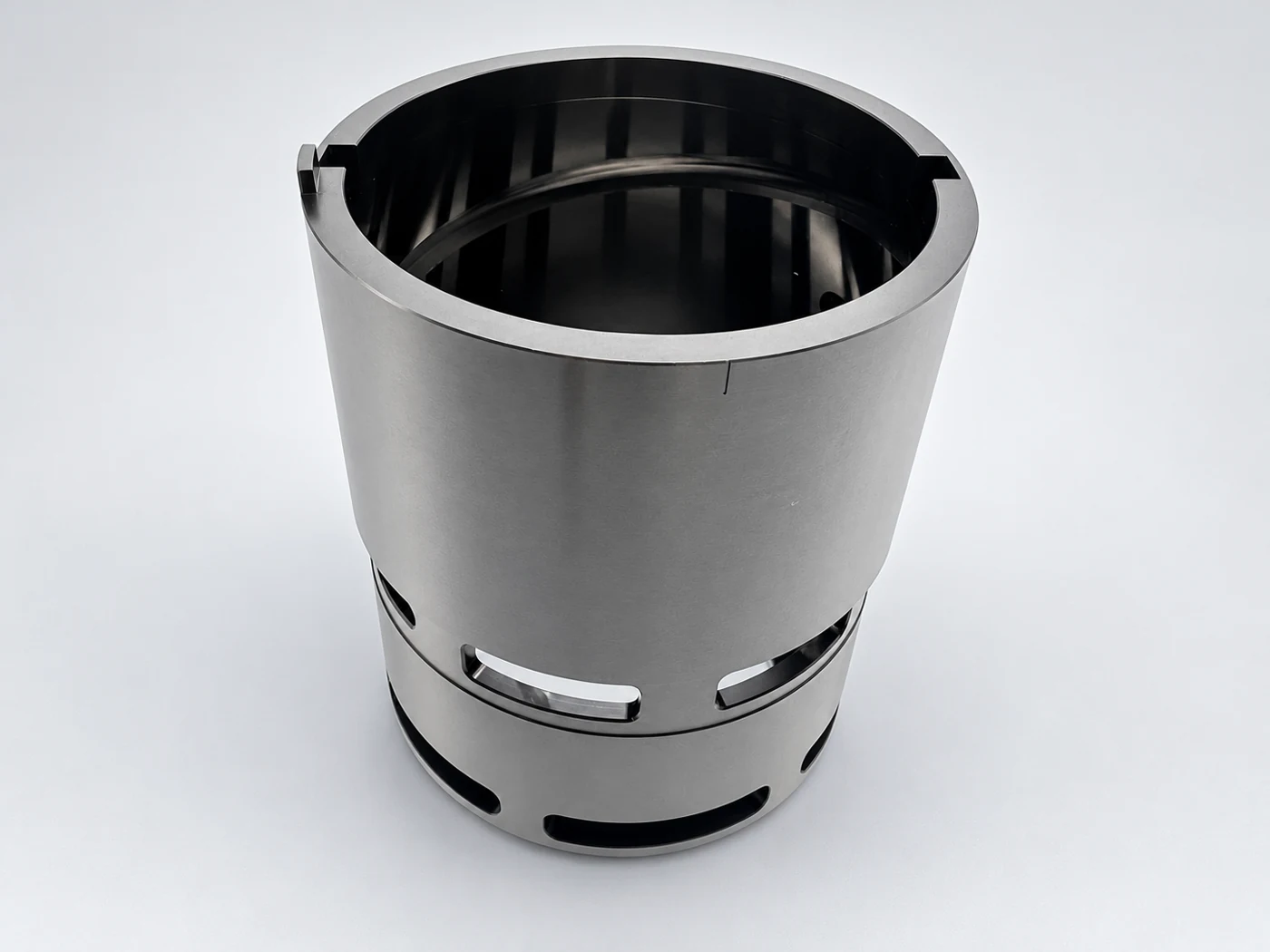
The sleeve combines cylindrical mating surfaces, side windows and rim notches. These openings interrupt the continuous wall, making the support state and the sequence of cylindrical finishing and window machining closely related.
Excess clamp force can temporarily change the circular section.
Evaluate distributed or internal support and verify the released state after critical machining.
Cutting windows changes the stiffness available for later operations.
Plan cylindrical finishing and window cutting as a linked sequence rather than unrelated operations.
Choose distributed or internal support around the functional surfaces and control the clamping load.
Keep the end and angular datums connected when machining windows and rim notches; account for the change in stiffness.
Inspect both sides of the window edges and measure the specified cylindrical sections in the required support condition.
Check drawing-defined bore/outer dimensions and any specified form requirement in the agreed released state.
Assess the cylindrical fit in the required released condition.
Measure axial and angular locations from the defined end and orientation references.
Keep the openings aligned with the mating structure.
Inspect both internal and external edges with a viewing method that reaches the inner wall.
Avoid loose burrs and damaged functional lips.
Prevent radial compression and keep slot edges from contacting adjacent parts during handling and transport.
Send your 2D drawing, 3D model, material and quantity. For this type of part, include: