
01
Paired bore relationship
CHALLENGE
Separate setups can preserve each hole size while losing their relative alignment.
PROCESS CONTROL
Where access permits, finish paired features from a shared reference and check their relationship explicitly.
Treat the paired bores and mounting base as one functional relationship.
Reference parameters
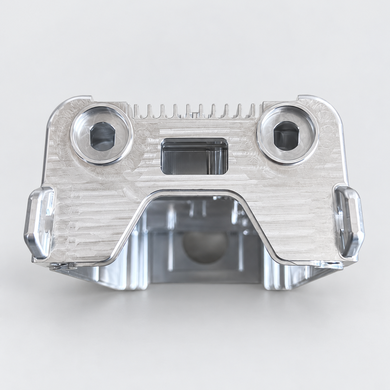
Two bored regions are joined across a central opening. The opening provides clearance but reduces support compared with a solid block; bore relationships and mounting-face geometry therefore need to be controlled together.
Separate setups can preserve each hole size while losing their relative alignment.
Where access permits, finish paired features from a shared reference and check their relationship explicitly.
Opening the centre changes how the arms respond to clamp force.
Balance roughing and preserve support before final bore and base finishing.
Define the specified relationship between the bores and mounting faces, then carry that datum system into each setup.
Balance rough stock removal and retain support near the bridge feet before finishing the functional features.
Finish the bores and base, deburr the opening and check the specified geometric relationships after release.
Measure the specified bore relationship against the common drawing datums.
Keep the bore relationship consistent with the drawing.
Check the specified mounting surfaces after releasing the fixture in the agreed support condition.
Maintain the intended mounting contacts.
Check clearance boundaries and burr removal without rounding functional locating edges.
Preserve clearance without damaging functional edges.
Support both feet during transport and keep external loads off the open bridge span.
Send your 2D drawing, 3D model, material and quantity. For this type of part, include: