
01
Asymmetric stock removal
CHALLENGE
The offset shape loses stiffness as its pockets open up.
PROCESS CONTROL
Retain useful support stock during roughing and plan the finishing sequence around the final mounting faces.
Keep the two mounting ends aligned across an offset, pocketed arm.
Reference parameters
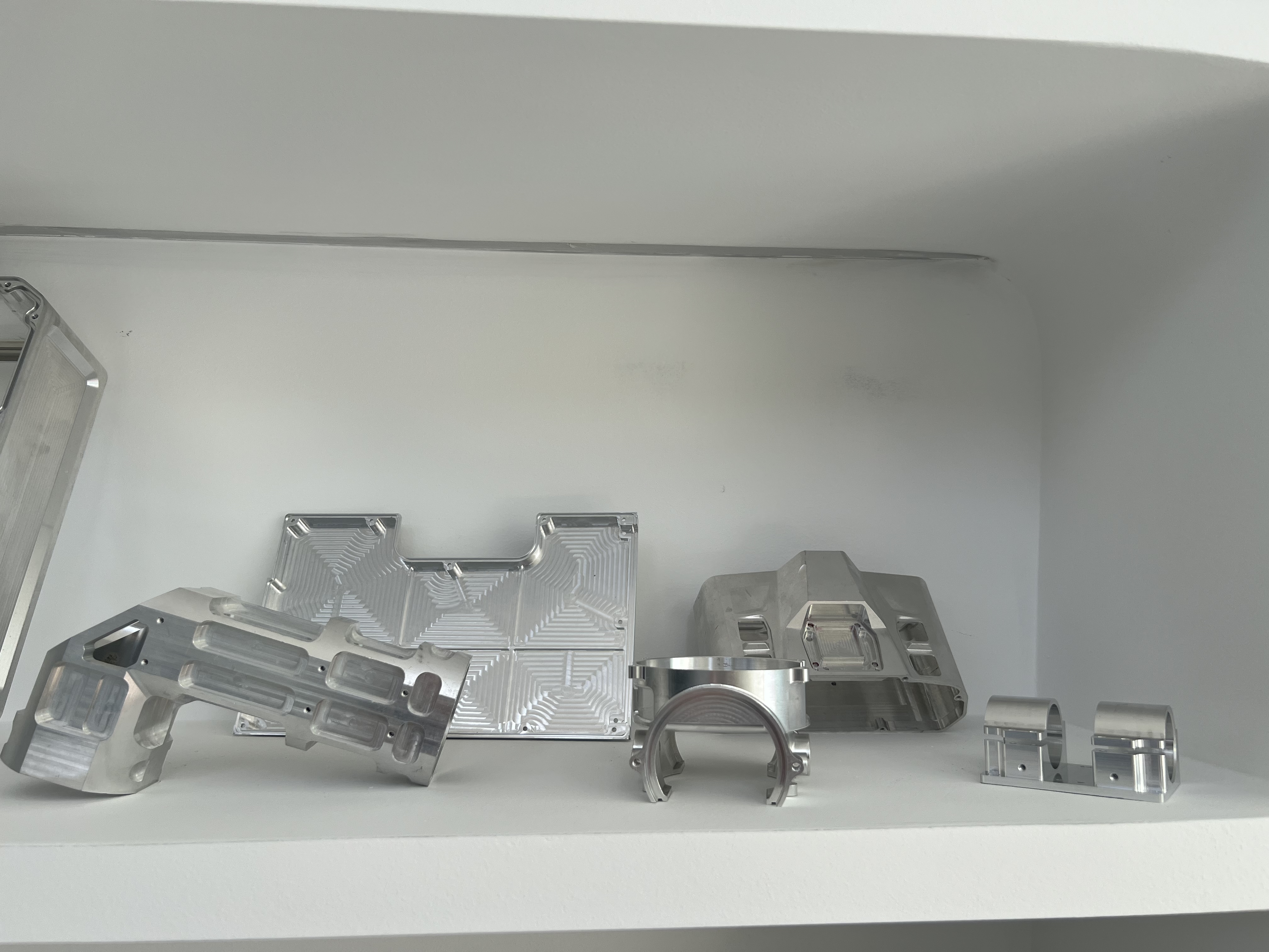
The offset arm combines mounting ends, weight-relief pockets and connecting ribs. The manufacturing focus is the relationship between the two mounting regions: pocket machining changes the support available for finishing the interfaces.
The offset shape loses stiffness as its pockets open up.
Retain useful support stock during roughing and plan the finishing sequence around the final mounting faces.
Locating each face independently can accumulate error between the two mounting ends.
Carry references between setups and make fixture support avoid unsupported arms and pocket edges.
Identify the mating faces and hole groups at both ends; choose locating and clamp-contact areas that remain available across setups.
Remove the pocket stock in stages, preserving the stiffness of the connecting ribs and leaving stock for the final interfaces.
Carry the datum system into the final setups, deburr the pocket transitions and check the mounting relationships after unclamping.
Check the specified planes and hole pattern from a common datum using a suitable CMM setup.
Keep both ends aligned with the mating assembly.
Check specified wall sections and accessible pocket transitions; distinguish clearance from mating surfaces.
Preserve the required rib sections and clearance boundaries.
Recheck critical interfaces in the agreed support condition after releasing the clamps.
Distinguish released-part geometry from clamp-induced distortion.
Support the arm during handling and isolate both mounting ends; do not stack weight on the offset span.
Send your 2D drawing, 3D model, material and quantity. For this type of part, include: