All machining cases
Electronics & communications

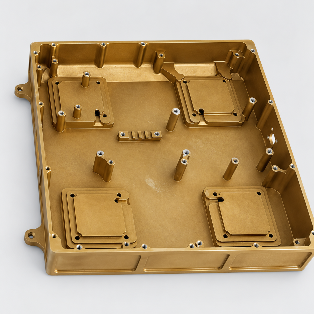
Partitioned electronics housing

Relate internal mounting heights to the continuous cover flange.

Reference parameters

Quantity reference
500 pieces
Material reference
6061-T6
Overall size reference
320 × 240 × 55 mm
Tolerance reference
±0.05 mm
Finish / condition reference
Conversion coating
Discuss a similar part
Partitioned electronics housing
01 · PART GEOMETRY

Internal mounting levels meet the cover interface

The housing combines separated cavities, mounting bosses and a continuous perimeter flange. The bosses locate internal components while the flange supports the cover, so these features need one connected dimensional strategy.

  • Bosses and cover flange
  • Mounting-hole pattern
  • Treatment-sensitive interfaces
02 · MACHINING CHALLENGES

Where geometry shapes the machining approach

01

Thin partition walls

CHALLENGE

Removing most material on one side first can leave an unbalanced wall section.

PROCESS CONTROL

Evaluate a staged pocket sequence, retain finishing stock and avoid using unsupported partitions as clamp-contact points.

02

Boss-to-rim relationship

CHALLENGE

Independent size checks may miss the relationship between internal mounting levels and the cover plane.

PROCESS CONTROL

Measure both against the same agreed reference and include cover-interface review in first-article planning.

03 · MANUFACTURING APPROACH

From locating datums to finished interfaces

  1. 01

    Establish the enclosure datums

    Connect the bottom mounting features, boss levels and cover flange in the setup plan.

  2. 02

    Separate cavity roughing and corner finishing

    Open the cavities while retaining wall support; select corner tools around the specified internal radii and available reach.

  3. 03

    Finish the assembly interfaces

    Finish boss tops, mounting holes and the cover interface; include any specified masking and final-condition checks in the finishing plan.

04 · INSPECTION FOCUS

Check the features that govern assembly

01

Bosses and cover flange

Inspection method

Measure boss heights and the specified flange flatness from the drawing datum.

Functional purpose

Maintain internal component height relative to the cover.

02

Mounting-hole pattern

Inspection method

Check hole positions relative to the board layout and cover; use mating parts for a separate assembly check when supplied.

Functional purpose

Align mounting patterns with the boards and cover.

03

Treatment-sensitive interfaces

Inspection method

Check the specified masking boundaries and final mating areas after the required surface treatment.

Functional purpose

Preserve mating areas through finishing.

Explore inspection planning
05 · HANDLING & DELIVERY

Protect the interfaces through handling and packing

PROTECTIVE HANDLING

Protect the flange and bosses separately and retain the treatment-batch reference with the inspection records.

YOUR NEXT PROJECT

Have a similar component?

Send your 2D drawing, 3D model, material and quantity. For this type of part, include:

  • Board layout, mounting heights and cover interfaces
  • Permitted internal radii and confirmed surface-treatment specification
Upload drawings for a quote
Electronics & communicationsDeep enclosure with a perforated dividerRobotics & automationOffset pocketed support bracketOptics & sensingMulti-aperture curved shell