
01
Radial support stability
CHALLENGE
Opening the spaces between arms reduces stiffness during machining.
PROCESS CONTROL
Retain support during roughing and evaluate the release sequence before finishing the central reference.
Connect the centre bore to the outer mounting pattern across the open radial structure.
Reference parameters
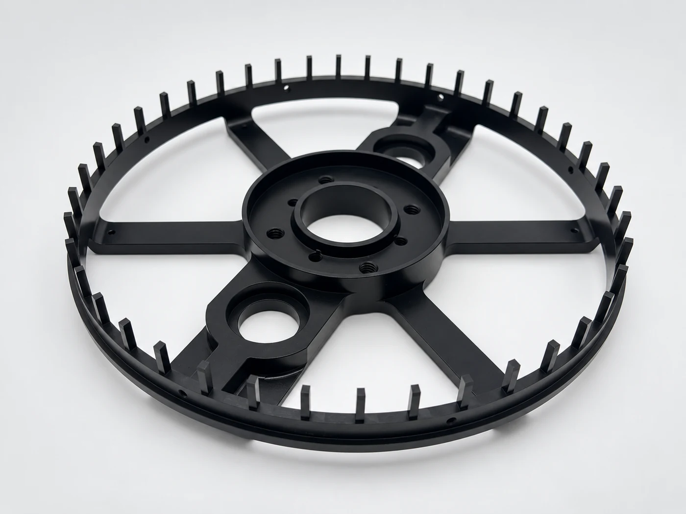
A central hub, radial members and outer mounting features form an open ring structure. The key is their relationship: the centre interface and outer pattern need to remain connected as material is removed from the radial sections.
Opening the spaces between arms reduces stiffness during machining.
Retain support during roughing and evaluate the release sequence before finishing the central reference.
Checking bore size alone does not establish its position relative to the mounting pattern.
Tie the hub and outer features to a common datum plan and inspect the relationship as a system.
Locate the hub, end face and outer mounting pattern within one datum system.
Plan the removal of stock around the open sections so the remaining ribs are supported during finishing.
Finish the centre and outer features, treat accessible edges and check the final mating condition required by the drawing.
Check the centre bore and outer mounting pattern together using the drawing datum system.
Align the centre interface with the outer mounting pattern.
Measure specified face geometry under agreed support without forcing the ring flat.
Verify face geometry without forcing the ring flat.
Inspect accessible openings and check protected mating features in their specified final condition.
Protect mating features and exposed radial edges.
Part number and revision → feature and datum → sample and batch → instrument and measured result. Agree the required records with the order.
Review inspection recordsProtect the radial ribs and separate the finished faces; avoid gripping or hanging the part by unsupported fins.
Send your 2D drawing, 3D model, material and quantity. For this type of part, include: