
01
Long narrow geometry
CHALLENGE
Unsupported spans may move during pocketing or release after clamping.
PROCESS CONTROL
Support the panel along its length and balance material removal before the final profile pass.
Control connector fit and the visible blue finish in the same final condition.
Reference parameters
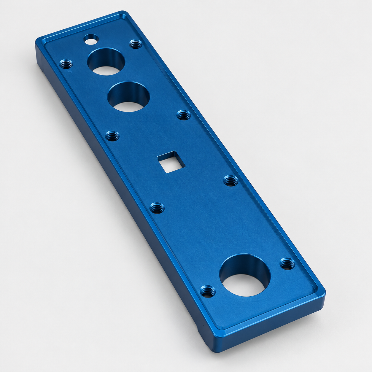
The elongated panel combines round holes, shaped openings and a blue visible face. The openings serve as both assembly interfaces and visible edges, making support, edge treatment and handling part of the same manufacturing task.
Unsupported spans may move during pocketing or release after clamping.
Support the panel along its length and balance material removal before the final profile pass.
Tool marks, burrs and handling scratches become conspicuous on a coloured front face.
Control edge preparation before treatment, agree fixture-contact positions and isolate finished panels during transfer.
Choose clamp-contact areas away from the visible face and keep the panel supported as the openings are machined.
Link each opening to its connector geometry, retaining specified corner radii and edge conditions.
Define visible zones and masking before the specified finish; check the openings and protect the face during subsequent handling.
Check the mixed aperture shapes and spacing; use the relevant connector or gauge where agreed.
Allow connector installation without forcing the panel.
Check specified flatness or straightness in the agreed free or supported state.
Check the panel in its intended assembly condition.
Compare with the approved appearance reference under consistent lighting and check masked interfaces.
Keep visible appearance and functional interfaces consistent.
Use separators between panels and keep the approved color-reference version with each finishing batch.
Send your 2D drawing, 3D model, material and quantity. For this type of part, include: