
01
Bend sequence and access
CHALLENGE
A previously formed wall may obstruct a later bend.
PROCESS CONTROL
Evaluate tool clearance across the complete sequence and retain a feasible order for the return walls.
Review the finished folded shape, not only the flat blank.
Reference parameters
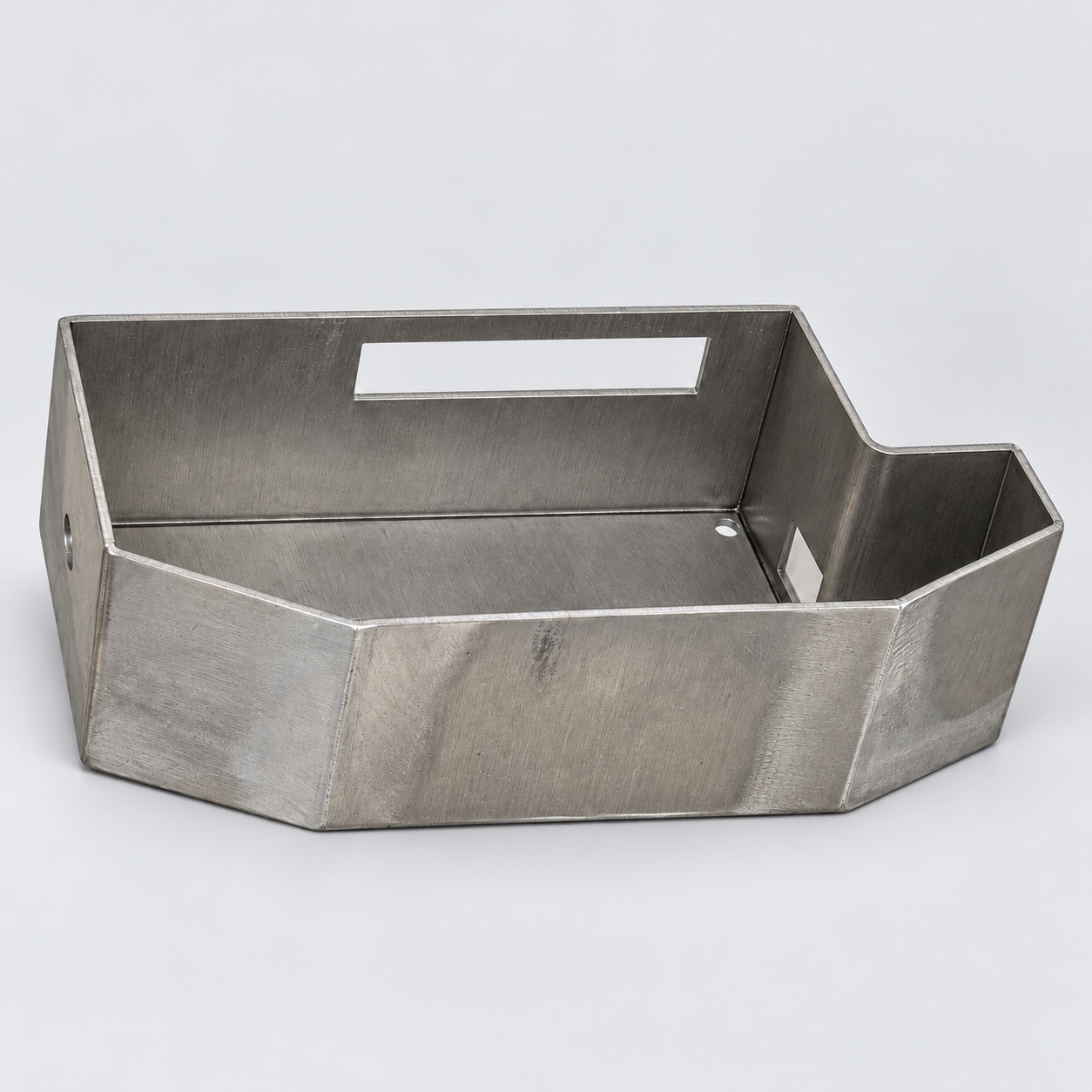
The tray has an irregular perimeter, folded walls and access openings. The flat pattern must translate into a usable enclosure interface, with enough clearance for the tooling and for the components fitted inside.
A previously formed wall may obstruct a later bend.
Evaluate tool clearance across the complete sequence and retain a feasible order for the return walls.
An opening can change position or distort if its relationship to the bend is overlooked.
Review opening-to-bend distances and inspect the openings in the final formed condition.
Review material thickness, bend radii, reliefs and openings near bend lines as one layout.
Plan the order of wall forming to retain tool clearance and check features vulnerable to distortion near each bend.
Check angles, wall positions and opening geometry in the formed state; deburr accessible edges before protective packing.
Measure specified angles and overall dimensions after forming with suitable gauges or a fixture.
Keep the tray within the mating enclosure envelope.
Check opening locations and distortion in the final folded condition.
Check openings in their final formed position.
Check fit with the mating enclosure when available and inspect exposed cut edges for burrs.
Support assembly and handling without sharp-edge interference.
Support the base and separate side walls during packing; avoid forced nesting that spreads the folded walls.
Send your 2D drawing, 3D model, material and quantity. For this type of part, include: