
01
Heat and material response
CHALLENGE
Local heating can change the cutting response and make a freshly machined dimension misleading.
PROCESS CONTROL
Use a heat-conscious cutting sequence and establish a consistent condition for final measurement.
Check the stepped locating opening after the plastic has reached the agreed measurement condition.
Reference parameters
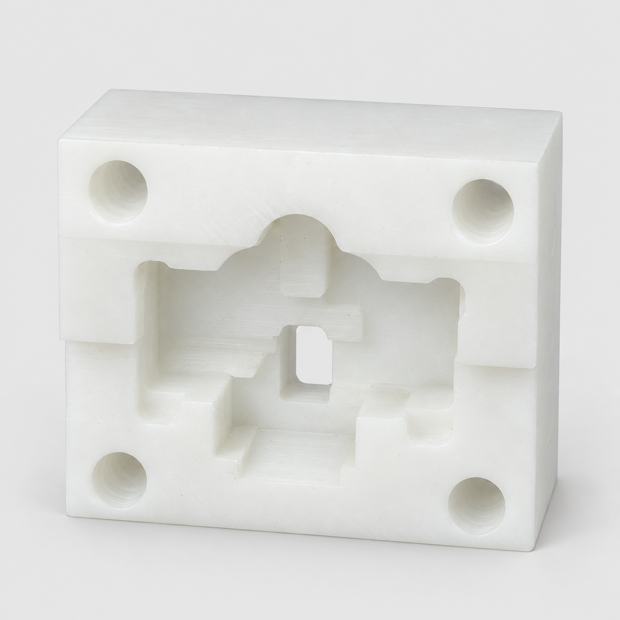
The block combines a stepped, non-circular opening and four corner mounting holes. Their relationship defines the locating geometry, while the plastic material makes heat input, clamping force and measurement conditions especially relevant.
Local heating can change the cutting response and make a freshly machined dimension misleading.
Use a heat-conscious cutting sequence and establish a consistent condition for final measurement.
A compliant polymer part can be distorted by clamp force even when its outer faces look flat.
Use distributed support and controlled clamping; verify critical fits after release.
Support the block across suitable areas and avoid concentrated clamping at the functional opening.
Use suitable sharp tooling and adequate chip clearance to limit heat accumulation during pocket and profile machining.
Finish the steps and mounting holes, remove edge burrs without rounding locating surfaces and measure under consistent conditions.
Measure the specified contour and depths using a suitable optical or low-force contact method.
Retain the intended locating contacts.
Check the mounting-hole pattern against the locating opening in the same reference setup.
Connect the mounting pattern to the locating opening.
Inspect functional shoulders after unclamping and deburring, avoiding force that distorts the part during measurement.
Avoid treating clamp or measuring-force deflection as part geometry.
Keep material batches identifiable and avoid sustained stacking loads on the locating opening and shoulders.
Send your 2D drawing, 3D model, material and quantity. For this type of part, include: