All machining cases
Optics & sensing

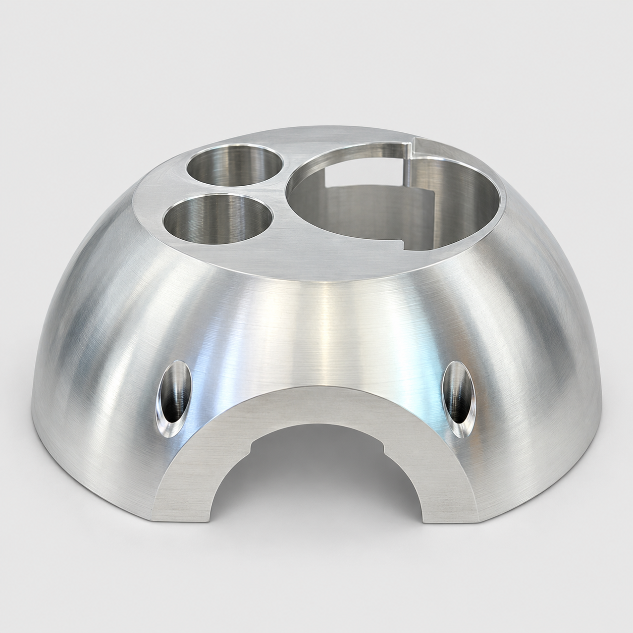
Multi-aperture curved shell

Coordinate the curved envelope, angled apertures and lower mounting clearance.

Reference parameters

Quantity reference
1000 pieces
Material reference
6061-T6
Overall size reference
150 × 130 × 85 mm
Tolerance reference
±0.05 mm
Finish / condition reference
Fine-machined surface
Discuss a similar part
Multi-aperture curved shell
01 · PART GEOMETRY

A curved envelope with apertures in several directions

The shell combines an external curved surface, apertures at different orientations and a lower clearance cutout. Its shape calls for a coordinated approach to surface machining, aperture alignment and access around the lower opening.

  • Curved outer profile
  • Aperture locations and axes
  • Edges and assembly clearance
02 · MACHINING CHALLENGES

Where geometry shapes the machining approach

01

Curved surface support

CHALLENGE

Clamping a finished curved face can create local marks or move the part under load.

PROCESS CONTROL

Use the installation features to establish references; evaluate shaped supports and permitted clamp-contact areas before finishing the exterior.

02

Apertures in different directions

CHALLENGE

Repeated reorientation can accumulate location error between the apertures and lower mounting features.

PROCESS CONTROL

Plan orientations from a shared reference system and check tool and fixture access at each aperture rather than treating every hole as a separate drilling job.

03 · MANUFACTURING APPROACH

From locating datums to finished interfaces

  1. 01

    Plan support and machining orientations

    Locate from the installation features and check tool, holder and fixture clearance for each aperture.

  2. 02

    Prepare a consistent finishing allowance

    Separate roughing, semi-finishing and finishing around the curved envelope to control the remaining stock and toolpath transitions.

  3. 03

    Connect the apertures and clearance cutout

    Machine the openings from the defined datums, then inspect the inside edges and lower clearance against the mating geometry.

04 · INSPECTION FOCUS

Check the features that govern assembly

01

Curved outer profile

Inspection method

Compare specified surface points or sections with CAD using an appropriate coordinate or profile measurement method.

Functional purpose

Keep the envelope consistent with the assembly space.

02

Aperture locations and axes

Inspection method

Check apertures against a shared reference system, including their relationship to the lower locating features.

Functional purpose

Relate each aperture to the installation features.

03

Edges and assembly clearance

Inspection method

Inspect inner aperture edges and check clearance with a supplied mating model or component.

Functional purpose

Prevent edge interference at assembly.

Explore inspection planning
05 · HANDLING & DELIVERY

Protect the interfaces through handling and packing

PROTECTIVE HANDLING

Separate curved faces and aperture edges in packaging; identify the drawing revision used for the interface checks.

YOUR NEXT PROJECT

Have a similar component?

Send your 2D drawing, 3D model, material and quantity. For this type of part, include:

  • Cover CAD, mating assembly and aperture-axis requirements
  • Defined cosmetic zones, edge conditions and inspection datums
Upload drawings for a quote
Optics & sensingSlotted thin-wall sleeveRobotics & automationOffset pocketed support bracketElectronics & communicationsPartitioned electronics housing