
01
Tool reach inside the cavity
CHALLENGE
Long tool reach increases sensitivity to tool deflection and chip recutting.
PROCESS CONTROL
Split roughing and finishing by reach and preserve sufficient clearance for chip removal.
Plan tool and probe access before the deep pockets and divider restrict it.
Reference parameters
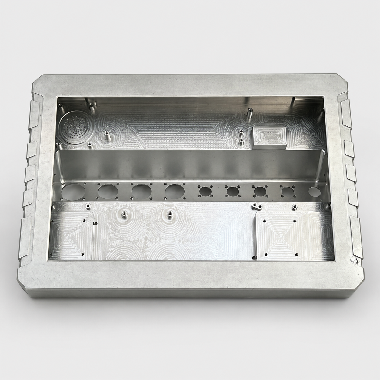
The deep body and perforated divider create several machining and mounting levels. Tool reach, probe access and chip removal are connected decisions: an accessible outside shape can still conceal difficult internal edges.
Long tool reach increases sensitivity to tool deflection and chip recutting.
Split roughing and finishing by reach and preserve sufficient clearance for chip removal.
A completed wall may obstruct the tool or the deburring path.
Sequence divider features before access is restricted and review the actual tool envelope.
Review the section geometry and the approach paths for cutters, probes and deburring tools before dividing operations.
Use the shortest practical tool assembly at each depth, clear chips between levels and schedule divider features while access remains available.
Finish the mounting levels and cover interface from the enclosure datums, including inspection of hole exits and hidden cavity edges.
Use an accessible probe configuration to check mounting levels and divider positions from the enclosure datums.
Keep separate mounting levels in one datum system.
Inspect both reachable sides of the openings and plan a suitable viewing method for concealed edges.
Avoid loose burrs and obstructed passages.
Check the specified cover interface and internal envelope against the assembly requirements.
Preserve the required space for internal components.
Remove trapped chips before packing; support the enclosure at its base rather than loading the thin upper rim.
Send your 2D drawing, 3D model, material and quantity. For this type of part, include: